




Compact scanner with its own screen & battery. Runs from a compatible phone, tablet or computer. Blue-laser accuracy up to 0.03 mm · objects from 10 mm Metrology-grade handheld for demanding reverse engineering, blue laser + NIR dual mode. Accuracy up to 0.02 mm · min scan volume 5 mm markers & manual turnable available in the store. Every restoration hits the same wall. The original part is discontinued and used replacements are difficult to find, while the one still bolted to the car is often cracked. A handheld blue-laser scanner can capture that geometry, though how long it takes depends on the part, its surface and how you set up. A desktop printer can then produce a fitment prototype without dedicated moulds or dies. What still goes wrong is everything around the scanning: surface preparation, the jump from mesh to CAD, material choice. Two scanner categories can serve many restoration projects, and the full scanner comparison shows what separates them. Every figure below comes from Creality's published specifications for the two machines. Two rows decide most purchases, and neither is the one buyers ask about first. The Raptor is a powered USB 3.0 scanner. The standard set runs from a Windows or macOS computer, and wireless operation needs a compatible accessory such as the Scan Bridge, sold separately. That accessory removes the cable. It does not turn the Raptor into a self-contained scanning and processing station. The Pika carries its own screen and battery, but Creality's FAQ still specifies a phone, tablet or computer to operate it. Plan to bring a compatible processing device: a laptop for the Raptor, a supported phone, tablet or computer for the Pika [1][2]. Compatible is doing real work in that sentence. The Pika's published device requirements are specific: Android with a Snapdragon 8 Gen 2 or newer and at least 8 GB of RAM, or an iPhone with an A15 chip or newer and at least 6 GB of RAM. iPhone does not support the wired connection mode at all. Some scanning modes are available only when the scanner is cabled to a computer, so a phone-only setup reaches a subset of the feature set. Check Creality's current device list against your own phone or tablet before you buy, not after. Object range is the manufacturer's nominal span for object size, not a promise of capturing something that large in one pass. A two-metre panel gets scanned in sections and merged. The manual is also specific about how the accuracy figures were produced: evaluated in laboratory conditions against a 100 mm sphere-pair artefact, with real results affected by temperature, vibration and technique [1]. The Pika page states laboratory conditions [2]. Published scanner accuracy figures are typically obtained under controlled test conditions, and the exact setup can differ between manufacturers and measurement methods. In practice it means accuracy is something you hold through working distance, calibration and fixturing, rather than a property that transfers on its own to a 400 mm casting. Steps 2 and 3 are about that. For automotive parts, accuracy and resolution both matter. Resolution decides how much surface detail can be captured. Accuracy decides how far the measured dimensions sit from the real ones. Fitment also depends on volumetric accuracy, hole positions, alignment error and what happens afterwards in CAD. Mounting holes, sealing surfaces and mating edges should be checked by measurement rather than inferred from a point cloud. For hobby restoration projects built from trim pieces, clips, brackets and small castings, the Pika keeps the setup compact. Its published blue-laser accuracy is up to 0.03 mm under laboratory conditions, and that mode covers objects from 10 mm up. It supports compatible smartphones and tablets, though marker-free blue-laser scanning is available only in wired PC mode. The Raptor suits more demanding reverse engineering: finer local detail in blue-laser mode, a 5 mm minimum scanning volume, and NIR scanning at working distances of 170–1000 mm for capturing larger body panels over multiple passes, where it can track by geometry or texture instead of markers [1]. Choose according to part size, required dimensions, scanning environment and budget. Current pricing and promotions are available on the linked EU product pages. Three questions decide whether to start. Design patents protect how a part looks. Utility patents protect how it works. For many exterior replacement panels, such as bonnets, fenders, bumpers and headlamp housings, preserving the car's original appearance is an important requirement alongside fitment and functional performance. That combination is also why design rights attach to these parts so readily. In the United States, the proposed SMART Act (H.R. 1707, 118th Congress) would have limited design-patent enforcement against certain aftermarket exterior replacement parts. Under the proposal, qualifying parts could be manufactured for repair, and their use or sale would become exempt from infringement liability after a 30-month period. It was introduced on 22 March 2023 and was not enacted [3]. France introduced a partial spare-parts repair exception on 1 January 2023, and it is narrower than it first appears. Copyright law covers certain replacement parts intended to restore a vehicle's original appearance (CPI art. L122-5, 12°). The exception under registered design law is more limited: it covers qualifying glazing components and certain replacement parts produced by the original equipment manufacturer (CPI art. L513-6, 4°) [4]. Independent manufacturers should not assume that every visible automotive component can be freely reproduced or sold. Trademark exposure is a separate question again, so a missing badge on the part is not a general defence. The EU has since adopted a broader reform, and it arrives in two instruments with two different clocks. Regulation (EU) 2024/2822, largely applicable since 1 May 2025, reforms the EU-wide design right and extends protection to certain activities involving digital files used to reproduce protected designs [12]. Directive (EU) 2024/2823 harmonises national design law instead. Article 19 introduces a repair clause for form-dependent components used solely to restore a complex product's original appearance, and it conditions that defence on telling consumers the commercial origin and identity of the manufacturer. Member States must transpose the Directive by 9 December 2027. In Member States whose laws protected qualifying replacement-part designs as of 8 December 2024, transitional protection for designs filed before that date may continue until 9 December 2032, subject to the Directive's conditions [11]. The digital-file point matters more here than the repair clause. Digital scan meshes and printable files may fall within the scope of design-right enforcement when they are used to reproduce a protected design without authorisation. Whether a particular activity actually infringes depends on the rights involved, the exceptions that apply, the purpose of the use and the jurisdiction. What does not wait until 2027 is that digital files are already covered by the Regulation's provisions, not only by the Directive still awaiting transposition. Personal, non-commercial restoration and commercial reproduction may be treated differently under applicable law. Check local intellectual-property and vehicle-safety requirements before manufacturing or selling replacement components. Blue laser mode handles a lot of difficult material on its own. Creality states low dependence on scanning spray, and both machines pick up many black and metal objects untreated [1]. Many is not all. Highly reflective, transparent and deeply recessed surfaces can present challenges for optical scanning, and depending on the scanner, the material and the lighting, you may need additional surface preparation or a different scanning technique. Chrome, polished aluminium, glass, gloss-black plastic and deep pockets are the usual suspects: the light reflects off in a focused direction, passes straight through, or bounces around inside the cavity and returns as artefacts [5]. A matting layer solves that in minutes, and the published numbers are simple enough to plan around. AESUB blue lays down 8–15 µm, gives a usable scan window of one to two hours and is gone in about four. AESUB orange lays down 2–6 µm, holds a window of four to eight hours and disappears in twelve to twenty-four. Both are pigment-free, self-vanishing sprays designed to reduce post-scan cleaning, though surface compatibility should still be checked against the manufacturer's application guidance [5]. Treat it as a flammable aerosol, not as harmless dust. AESUB blue is classified as an extremely flammable aerosol and its safety data sheet requires avoiding inhalation. Apply it in a well-ventilated area, away from flames, sparks, hot surfaces and other ignition sources. Follow the manufacturer's safety data sheet, let the coating dry before scanning, and test compatibility on painted, coated or historically valuable surfaces before you commit a whole panel [5]. A workshop with a space heater, a grinder and a spray can in the same corner is the exact scenario that sheet is written for. Markers are where the two machines differ, and it matters for small work. The Raptor's blue-laser mode uses marker-based alignment. The Pika also supports marker-free blue-laser scanning when it is connected to a computer by cable [2]. For small components, place reflective markers on a rigid fixture or a scanning mat whenever possible, because markers on a measured surface leave holes you have to interpolate. Reflective, featureless or geometrically awkward parts may still need markers directly on the surface to hold tracking [1]. One habit worth keeping: spray only the surfaces you are about to scan, and keep the faces you will measure with calipers untouched. A 5–15 µm layer is small, but it sits exactly where your tolerance check happens [5]. A handheld scanner is meant to be moved by hand. What it cannot tolerate is the part moving relative to the markers it is tracking against. When that happens, alignment drifts and the mesh comes out soft and smeared, which looks like a scanning fault and is usually a fixturing fault. Mount the part on a turntable or a fixed fixture, stay inside the working distance [1][2], and overlap passes by roughly a third as a starting point. How much overlap you actually need depends on how much feature the surface offers. Capture mating faces and hole axes deliberately, since those are what gets measured later. Very small parts are the difficult case, and the carrier-plate trick has limits. Mounting a tiny clip on a larger plate may improve tracking and alignment, but it does not overcome the scanner's minimum recommended scan volume or guarantee that fine detail comes through. For features below the specified range, macro photography, optical microscopy or direct dimensional measurement will serve you better than a scan [1][2]. A raw scan is a dense mesh with no design intent: no true planes, no concentric bores, no nominal dimensions. A mesh does not carry manufacturing intent either, and functional replacement parts usually need datums and verified critical dimensions. Parametric reconstruction in CAD is the step that turns a scan into a part. A differential cover for a 1980s rear-wheel-drive vehicle went through exactly that. The original was pressure die-cast, the replica was gravity sand cast, so wall sections were thickened to compensate for the lower density, and the CAD model was built to intended geometry rather than the worn one. Printed photopolymer patterns replaced metal tooling, and according to the project team the production cycle came in more than 60% shorter than with conventional tooling [6]. An NSU TT headlamp cover, whose model ended production in 1972, needed the opposite emphasis. The point cloud was corrected for age-related distortion first, because a direct copy would have preserved fifty years of warping. An aluminium punch-and-die set was then produced and validated by rescanning finished parts against both the CAD model and the original [7]. A BMW E36 Baur sunroof panel had a harder constraint: only a few hundred of these cars were built (BMW Group Classic gives 311) and no replacement panel existed. The roof and mounting areas were scanned on the car, modelled for OEM-style fitment, printed, and the finished part was reported to fit like the factory item [8]. Reverse-engineering software runs from general CAD that can reference a mesh to dedicated scan-to-CAD packages. Fusion can support manual reconstruction with the mesh as a reference. QUICKSURFACE and Geomagic Design X add purpose-built tools for fitting planes, cylinders and lofts to scan data. What separates them is not the manufacturing route, since a CNC bracket and a cast housing can each be modelled in any of them. It is model complexity, the tolerance the part has to hold, and how much editing comes after. Pricing varies by edition and licensing model, and it changes often enough that a number in a blog post goes stale, so check the vendor's current price list. Two things are worth knowing before you budget. Geomagic Design X is no longer a single enterprise-only licence: it ships in tiers, and the entry tier costs a fraction of the full package. On file interchange, STEP and IGES can carry curves, surfaces and solid models depending on how you export and how the model is built, but they do not normally preserve the complete native parametric feature history. Sending editable design history between CAD platforms usually needs dedicated integration tools rather than a file conversion. Heat deflection temperature is a useful starting point when selecting material for an under-bonnet component, but it does not establish long-term service suitability. Actual performance depends on operating temperature, mechanical load, thermal cycling, print quality and chemical exposure. The table below uses ISO 75 at 0.45 MPa, the load condition under which published figures are comparable [9]. Those numbers come from different suppliers, which matters more than it looks. The PLA, PETG, ASA and PC blend figures are Prusament datasheets, the ABS figure is Polymaker's PolyLite, and the 186 °C is Bambu Lab's PA6-CF. Polymaker publishes about 215 °C for its own PA6-CF: same nominal material, 29 °C apart. They are representative laboratory values for specific formulations, not a guarantee for every spool of the same polymer. Read the datasheet for the filament you actually bought. A high HDT is not a continuous operating temperature, and a low one is not an automatic failure. PA6-CF publishes 186 °C, but long-term performance depends on sustained load, print orientation, moisture uptake, creep and thermal cycling, none of which a short ramp test captures. A part sitting above its glass transition may still work in a lightly loaded application, and a part well below it can still creep under constant load. Evaluate the printed component under realistic conditions rather than picking one number off a table [9]. Location decides the rest. General under-bonnet ambient is one thing. The region near the intake manifold or the coolant hoses runs hotter, and areas close to the exhaust manifold may sit beyond the safe operating limits of common desktop filaments. Measure the actual temperature where the part will sit, then judge the material's long-term thermal and mechanical behaviour at that temperature rather than at the ambient reading. Fluid contact is a separate question with its own answer. Some engineering-grade polyamides are suitable for automotive fluid-contact applications, but compatibility depends on the specific grade, the fluid, the temperature and the manufacturing process. Standard desktop FDM prints should not be assumed to provide reliable sealing or pressure resistance, because layer porosity and bond strength are real limits even when they do not fail on the first fill. Fuel-system, brake-fluid and other safety-critical fluid-handling components require validated materials, processes and testing. A deviation map compares two sets of geometric data. It is worth being precise about which two, because three common comparisons answer three different questions. None of them independently establishes fitment or function. A deviation map will happily show a tight colour on a part that is dimensionally reasonable and functionally wrong, and matching a handful of critical dimensions is not proof that the whole component installs and performs. The cheap independent checks are still the useful ones. On a simple, non-safety-critical component, start with dimensional checks against the original and a trial assembly, then add thermal and functional tests where they are relevant, run under conditions you control. That combination will surface some of the dimensional, assembly and thermal problems. It will not establish long-term durability. How many measurements and which tests are appropriate depends on the part's geometry, what it does and where it will live. A load-bearing or safety-related part needs engineering validation suited to its intended use, because one assembly and one heat cycle say very little about fatigue, creep and vibration across a service life. Creality's own case study of Opimo 3D restoring a Mercedes-Benz 300SL reports roughly 25% better accuracy after the shop upgraded its scanning and printing workflow, along with a reported gain of more than 50% in production efficiency [10]. That is a project-level improvement across capture, modelling, fitment testing and iteration, not a controlled measurement of scanner accuracy. It is still the useful kind of number, because it describes what changes when the whole loop is tightened rather than one link in it. The scanner is an upfront equipment cost, with calibration, maintenance and consumables on top. Scanning spray is a consumable, and how far a can goes depends on part size, surface condition and the thickness of the coat. AESUB publishes a coverage figure of roughly 4 m² per can for Blue and Orange, which is a more useful basis for estimating than a can-per-part rule [5]. Reverse-engineering software is a licence decision rather than a purchase, and cost varies with the provider, the feature set, the subscription terms and whether a perpetual option exists at all. Verification can become a significant cost of its own, whether in workshop time, measurement equipment or professional testing. What inspection a part needs follows its function and its risk. A trial assembly or two, a thermal soak and a caliper check per feature cost evenings on simple parts; a load-bearing component can justify more. Skipping the checks is how a part that fits on the bench turns out not to fit on the car. A suitable 3D scanner can capture the bracket's geometry for reverse engineering, but its published accuracy does not guarantee that a manufactured replacement will meet the required tolerances. Mounting-hole positions, mating surfaces, material properties and mechanical loads all need independent verification, and a load-bearing replacement needs appropriate engineering validation. The standard workflow uses a Windows or macOS computer. A compatible Scan Bridge accessory enables wireless operation, but it does not turn the Raptor into a fully self-contained scanner [1]. The Pika has its own screen and battery and can run from a compatible phone, tablet or computer, but it still needs one of those devices [2]. Compatible is narrow here: Creality lists Snapdragon 8 Gen 2 class Android devices with at least 8 GB of RAM, or iPhones with an A15 chip and 6 GB. iPhone also does not support the wired mode, and the wired mode is what unlocks marker-free blue-laser scanning. No. Both machines scan many black and metal objects untreated, and blue laser mode is the better choice on those surfaces [1]. Chrome, glass, gloss-black plastic and deep pockets are where a matting layer earns its place [5], and where the aerosol precautions in Step 2 apply. It depends on the measured temperature at that location, the load it carries and how it was printed. A 93 °C HDT is a datasheet value under a short ramp at 0.45 MPa, not a service rating, and a 186 °C HDT is neither a continuous rating nor evidence that the part belongs next to the exhaust manifold [9]. Measure the installation environment and test the component you actually made. Not from an unvalidated desktop workflow. Some engineering polyamides are formulated for automotive fluid contact, but the grade, the fluid, the temperature and the process all have to match, and FDM layer porosity is a real sealing limit. Fuel-system and brake components require validated materials and testing. Visible exterior panels are where design rights bite. The US SMART Act was not enacted [3]. France's exception is partial and narrower for registered designs than for copyright [4]. The EU reform harmonises the position but attaches conditions, including telling buyers where the part came from [11][12]. Personal repair, commercial copying and sharing the print files are three different questions. Scan it for mounting geometry and the envelope, then source or mould the elastomer separately. Technical specifications, regulatory guidance and case studies cited above. Verify the most recent information before beginning a project.What Each Scanner Category Handles
Specification
Entry handheld (Pika)
Metrology handheld (Raptor)
Accuracy, blue laser
up to 0.03 mm [2]
up to 0.02 mm at 100 mm [1]
Accuracy, NIR
up to 0.1 mm [2]
up to 0.1 mm [1]
Minimum scan volume, blue laser
10 × 10 × 10 mm [2]
5 × 5 × 5 mm [1]
3D resolution, blue laser
0.1 – 2 mm [2]
0.02 – 2 mm [1]
Object range (nominal)
10 – 2000 mm [2]
5 – 2000 mm [1]
Working distance, blue laser
160 – 400 mm [2]
150 – 400 mm [1]
Working distance, NIR
140 – 1000 mm [2]
170 – 1000 mm [1]
Device connection
Phone, tablet or computer required [2]
Computer required for standard operation; compatible wireless accessories available [1]
Which Creality Scanner Should You Choose
Step 1: Screen the Part Before You Scan It
The Design-Patent Limit on Visible Panels
Step 2: Prepare Reflective, Glossy and Transparent Surfaces
Step 3: Secure the Part and Maintain Stable Scan Tracking
Step 4: The Scan Is a Template, Not a Part
Route
Sensible for
Key validation requirement
FDM print
brackets, clips, ducts, trim
load oriented along layers, layer adhesion checked
Resin print
fitment prototypes, detailed covers
a dimensional check before the part is trusted
CNC from aluminium
stressed brackets, mating faces
a model with datums and true planes, not a mesh
Casting from printed patterns
housings, small series
machining allowance and a first-article inspection [6]
Step 5: Choose the Material by Measured Temperature
Material
HDT at 0.45 MPa
PLA
55 °C
PETG
68 °C
ASA
93 °C
ABS
100 °C
PC blend
113 °C
PA6-CF (carbon-fibre nylon)
186 °C
Step 6: Verify Dimensions, Not Just the Colour Map
Comparison
What it establishes
Original scan mesh vs reconstructed CAD
whether the CAD model follows the captured geometry
Re-scan of the printed part vs the CAD model
whether the print reproduced the model
Printed part vs measured dimensions of the original
whether selected critical dimensions match the original reference
What the Workflow Costs
FAQ
Can an affordable scanner capture a gearbox mounting bracket accurately?
Can I use the Raptor without a computer?
Do I need to spray every part?
Will a printed part survive under the bonnet?
Can I print fuel or brake-fluid parts?
Can I sell the copies?
What if the part is rubber?
References & Further Reading
How to Replicate Discontinued Car Parts With an Affordable 3D Scanner
2026-11-10
How to Replicate Discontinued Car Parts With an Affordable 3D Scanner
2026-11-10
Entry handheld
Creality Pika 3D Scanner
Metrology handheld
CR-Scan Raptor
More scanners in our store
CR-Scan Ferret Pro — €349CR-Scan Otter — €628Otter Lite — €819CR-Scan Raptor Pro — €1,599Sermoon S1 — €2,159Sermoon P1S — €2,399Sermoon P1 — €3,499CR-Scan RaptorX — €3,699
Browse all scanners & engravers →0 COMMENTS
Tags
Share


Most People Read
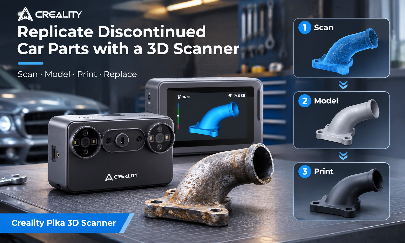
How to Replicate Discontinued Car Parts With an Affordable 3D Scanner
Scan a discontinued part, rebuild it in CAD, print it in the right plastic, and check the dimensions that decide fitment rather than the colour map.
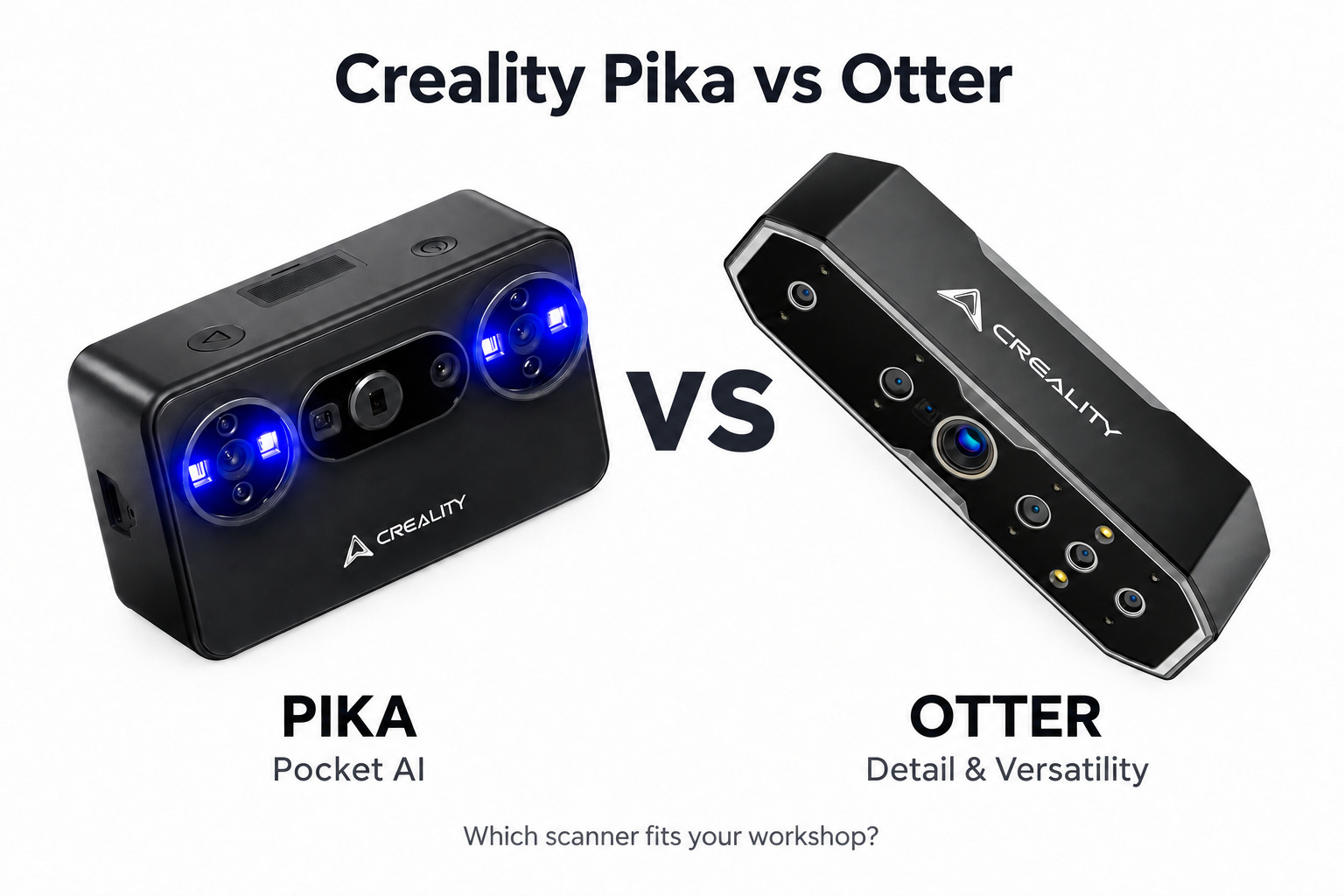
CR-Scan Otter vs Creality Pika: which scanner fits your work
Hands-on comparison of the Creality CR-Scan Otter and Pika: real accuracy at real working distances, frame rates by mode, and which jobs each one suits.
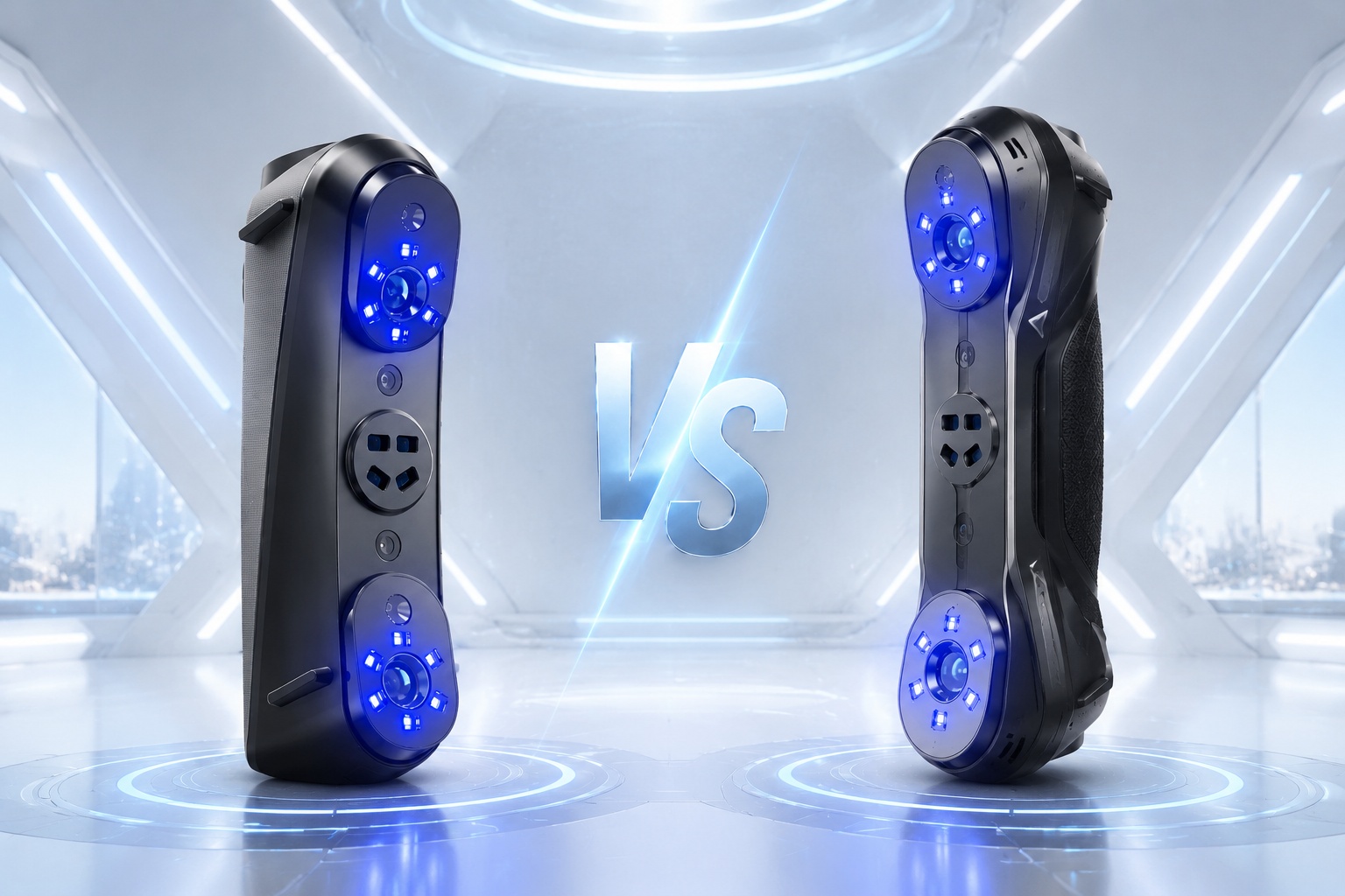
Sermoon S1 vs Raptor Pro: Best Blue Laser 3D Scanner for Reverse Engineering in 2026
Sermoon S1 vs Raptor Pro comparison. Discover differences in accuracy, scanning speed, laser modes, deep-hole scanning, and find the best 3D scanner for reverse engineering.